Part 1 - The Basics of Clocking
Clocking is an integral part of digital audio, and almost all audio products have a clock inside. As discussed in our previous series on digital to analogue conversion, digital audio recordings are made up of a series of samples. An audio product such as a DAC has to know when to do something with the samples it receives at its input, whatever this task might be – and this is where clocks come in.
In the context of digital electronics, the term clocking refers to a signal that keeps all of the circuits within a system in sync and operating at the same time. In order to generate a precise and reliable signal, the clock system must have a source: something that defines how long a period of time is. This source usually comes in the form of an oscillator – an electrical circuit that provides a regular rising and falling of voltage.
At dCS, we use quartz crystal oscillators as the basis for our clock systems. Quartz is a piezoelectric material, meaning that when a voltage is applied to it, it physically deforms and flexes back and forth. The crystal can be designed to resonate mechanically at a particular frequency (for example, every 44,100th of a second) and with a correctly designed electrical circuit, this resonance can be converted into an oscillating voltage.
The frequency of the crystal’s resonance lets a system know how long a specific increment of time (such as 1/44,100th of a second) is. Through measuring these increments of time, a system can accurately space audio samples apart. This avoids any unwanted movement of the samples in time, which, if it occurred during the digital to analogue conversion process, could cause distortion of the audio signal heard during playback.
The design of clocks in digital audio (both internal clock systems and external master clocks) is a topic worthy of serious consideration when purchasing any high-end audio system. Arguably, clocking can have as much of an impact on sound quality as DAC circuitry, and it’s vital to consider the design and implementation of the clocking system as a whole, rather than selecting simply selecting components that have an impressive specification on paper.
As the clock defines the timing of a DAC’s operations, it is responsible for ensuring the samples are converted at the correct time, which is crucial to ensuring the audio we hear during playback sounds as it should.
Jitter
If a clock system fails to produce a signal correctly during the D/A conversion process, or the signal is unable to correctly reach a DAC, then we experience something called jitter, which is highly undesirable in audio.
Jitter is described as any irregularity in the timing of the clock used by a DAC, and it is produced in a variety of ways. It can be the result of bad analogue design, electromagnetic interference, poor quality digital audio cable or a number of other causes, which we’ll discuss in future posts.
The actual audible effect of jitter depends upon its nature, but it can have a notable impact on sound. If jitter is periodic, sidebands will appear either side of the signal frequency. This sounds like a harsh distortion, as artificial components are being added to the audio. If the jitter is noisy in nature, this results in a ‘smearing’ of signal energy. This, in turn, increases the noise floor of a system, which has the effect of masking fine detail in the music.
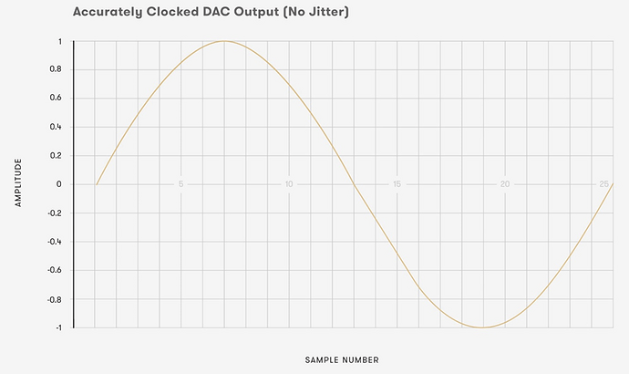
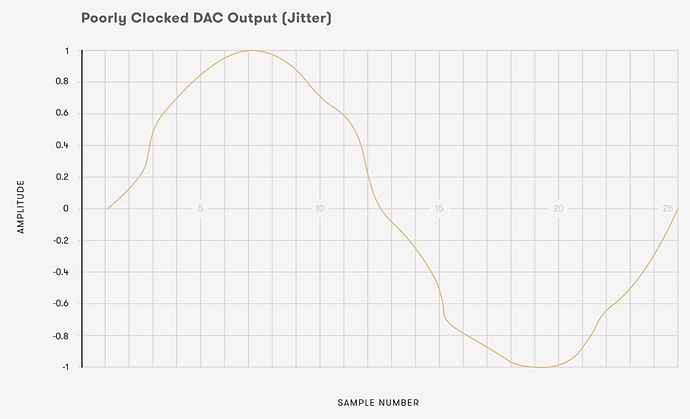
The above graphs show an example of what can happen with poor clocking. In both examples, a sine wave has been reconstructed by a DAC using 25 samples. Each of these samples has exactly the same amplitude in both graphs; the only factor which has changed is the timing of when several of the samples are converted. The result is a visible degradation of the signal. Were this signal to be played back through a transducer, the signal in the lower graph would sound noticeably worse than the top due to the jitter.
While the example above is rather exaggerated, it illustrates that the right sample at the wrong time is the wrong sample. This goes to show just how vital accurate clocking is to a digital audio playback system.
The human ear and brain are extremely sensitive to irregularities in the timings of sound. If a DAC experiences jitter, and fails to convert signals into analogue voltages at the correct time, then the sense of space in a performance can be heavily skewed or even lost. It’s for this reason that dCS engineers take great care to minimise jitter in all aspects of our design.
If jitter is introduced at the recording stage, it will remain in the signal forever. There are steps that can be taken to prevent further degradation of the signal (such as re-clocking or even buffering the signal into RAM and out again) but it isn’t possible to correct or remove jitter that arises during the recording process.
At the playback stage, jitter should be minimised wherever possible to avoid the signal we hear being compromised or altered. Provided a recording is of decent quality, having a DAC reproduce audio samples at exactly the right moment will help to ensure that listeners experience an accurate representation of the original sonic event. A signal coming into a DAC from an external source, such as a CD transport, can actually have very irregularly spaced samples on arrival (to a point, which we’ll cover in future posts), but provided the DAC itself converts those samples at regular intervals, the sound quality will remain unaffected.
Our next two posts will cover the main kinds of jitter: intrinsic and interface.

