Part 4 – The Ring DAC
How can the issues described previously with Ladder DACs be resolved? What would a DAC designed from the ground up to effectively de-correlate errors in the DAC itself and remove the resulting distortion look like? That is where the dCS Ring DAC comes into play.
The Ring DAC is the proprietary DAC technology found inside all dCS DACs. On the surface, the Ring DAC may look like a Ladder DAC. There is a latch and a resistor for each current source, and these current sources are fed to a summing bus. The key difference between the Ring DAC and Ladder DACs however, is that the Ring DAC uses current sources of equal value. This is what is known as a ‘unitary-weighted’ or ‘thermometer coded’ DAC architecture. Additionally, the Ring DAC does not use the same current source(s) for the same bit every time . There are 48 current sources within the Ring DAC, all of which produce an equal amount of current. The Field Programmable Gate Array (FPGA) controlled nature of the Ring DAC allows the sources to be turned on and off in such a way that any component value errors are averaged out over time. Firing the same bit three times on the Ring DAC might give one output slightly high, the next slightly low, the next somewhere in the middle, as opposed to outputting the sample slightly high every time, or slightly low every time (as seen in a Ladder DAC, for example).
It takes a considerable amount of signal processing power and know how to optimally operate a thermometer coded DAC, but the benefit with this approach is that it almost entirely removes the linear distortion from the signal (bear in mind that the highly artificial distortion many DACs produce is very noticeable to humans and has a negative impact on perceived sound quality).
The Ring DAC process may be thought of as decorrelating errors. Background noise (an uncorrelated error – one which is not linked to the audio signal itself) is very prevalent in nature, whereas artificial distortion (a correlated error) is not.
This results in the Ring DAC having class-leading distortion performance, particularly at lower signal levels. This means more fine detail can be resolved and heard in the audio.
The nature of exactly how the Ring DAC decides which current sources need to be turned on or off at any given point to generate the correct signal is dictated by a highly sophisticated set of rules defined in the dCS Mapper. While it may appear to be random, it is the culmination of three decades of continuous work, resulting in a carefully calculated set of patterns used to minimise noise, distortion and crosstalk while primarily keeping the highest degree of linearity by averaging out the contribution of components that fall out of specification over time. Improvements to the Mapper over time have allowed for a lower noise floor to be achieved, while maintaining the signature linear sound associated with the Ring DAC. The Mapper is what allows for the noise created by the Ring DAC to be pushed outside of the audible band of frequencies and then filtered out.
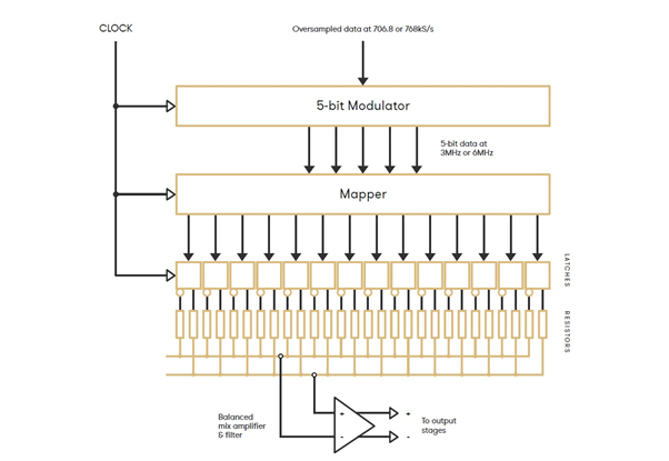
This diagram illustrates the basic layout of the Ring DAC.
The Mapper works at 5-bits, so PCM data which arrives at the Ring DAC is first oversampled to 706.8kHz or 768kHz. This is then modulated to 5-bits at a rate between 2.822MHz and 6.144MHz (depending on the unit, settings and content sample rate) and fed into the Mapper which distributes this signal to the current sources in the DAC.
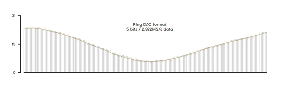
This diagram illustrates the output of the Modulator within the Ring DAC, modulating incoming digital audio signals to a 5-bit high rate format ready for conversion to analogue.
The next post will begin to discuss filtering in DACs.