Part 3 – Introduction to D/A Conversion
DACs – Digital to Analogue Converters – are a crucial part of almost all modern headphone setups, in one form or another. They play a vital role in helping to translate the original musical performance of an artist to a listening experience for the end user. The fundamental concept of a DAC is to translate digital audio – whether it is streamed from Spotify or Tidal, stored on a DAP or played from a NAS – into an analogue voltage which is used to drive a transducer like headphones.
When making this digital to analogue conversion, there are two factors to consider: can the converter perfectly reproduce the original amplitude of the wave when it was recorded (in other words, can it output the right voltage), and can it do it at exactly the right time? Whether the converter can reproduce the correct voltage comes down to the DAC circuitry itself, and whether it converts the sample at the right time comes down to the clocking of the system. I will go through the DAC circuitry first, and clocking definitely warrants its own topic which we plan to cover next.
Digital audio is stored in binary format (effectively a series of 1s and 0s) as a series of ‘samples’. As we discussed earlier, the number of consecutive binary digits that are used to represent the original sound wave is called the bit depth. 16-bit audio, for example, has 16 consecutive binary digits, all either 1 or 0. A DAC needs to translate this binary number to an analogue voltage, as that voltage is what drives headphones to produce sound. It does so using a series of current sources – electronic components that each generate an amount of analogue voltage.
One of the most common approaches to D/A conversion is to have one current source always working for one of the digital audio bits exclusively. For example, one current source will always be following what the first bit in the digital audio signal is doing. Another current source will always be following what the second bit in the digital audio signal is doing, and so on for as many current sources as are needed. As the current sources go on, the amount of energy they must generate gets smaller and smaller (it halves for each consecutive current source).
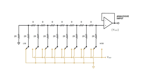
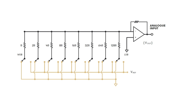
When looking at a diagram of how these components would be laid out, it looks an awful lot like a ladder, hence the informal name these types of DACs have been given – Ladder DACs. To ensure that the voltage generated by each current source is incrementally smaller the further down the chain they are, resistors need to be used between current sources. The values and layout of these resistors gives name to the two prominent types of Ladder DACs – R-2R DACs and Binary Weighted DACs.
One very important distinction to make early on – a dCS DAC (the Ring DAC) is not a Ladder DAC. This difference will be explained later.
R2R DACs
R-2R DACs (a subset of Ladder DAC) use one of two resistor values to control the amount of voltage generated by each current source. Resistors of value R are used between each current source section, and resistors of value 2R are used on each current source. If a particular bit in the audio signal goes high (a 1 instead of a 0), the corresponding switch is enabled and that current source output goes high. The outputs of all current sources are then fed to a summing bus, which provides the overall output of the DAC.

Binary Weighted DACs
In Binary Weighted Ladder DACs, resistors of decreasing values are used to create increasingly small steps in power generated by current sources. If the first resistor has a value of R, the next would be 2R, then 4R, then 8R, 16R, and so on for as many steps as required. This hierarchy of resistor values is what gives this approach the Binary Weighted name.

The main drawback with both the R-2R and Binary Weighted DAC approaches comes from the fact that resistors (like all electronic components) have an element of error in their values. For example, a gold tolerance resistor guarantees the resistance of the component will be within 5% of its stated value. This means that for the resistors used in a Ladder DAC, the current generated by that section of the DAC could be either lower or higher than needed. The key point here is that a Ladder DAC uses the same current source for a given bit in the audio signal every time, meaning the error is exactly the same every time the bit goes high. Here, the errors in the component values are correlated to the audio signal. This results in an audible linear distortion of the signal, adding in unwanted harmonic components.
The issue with this is the fact that the larger current sources (correlating to the more significant bits in the audio signal) have the same margin of error as the smaller ones. In the case of a 24-bit ladder DAC, a 1% error in the most significant bit (MSB, or the largest current source) would be larger than the entire 7th bit, and 104dB louder than the 24th bit. The MSB needs to be accurate to 0.000006% to allow for 24-bit resolution.
One further issue Ladder DACs suffer from is Zero Crossing Point Distortion. Given that each current source has a potential correlated error associated with it, what happens when say in a 16-bit DAC we go from reproducing an amplitude of 32767 to 32768? The DAC changes from having the first (most significant) bit low and the following 15 bits high, to having the first bit high and the following 15-bits low. This is called the Zero Crossing point. The size of the errors associated with each current source / bit here – specifically the fact that the sum of the 15 errors with 32767 and the one error with 32768 – are both very large compared to the least significant bit (LSB). This means that the change from 32767 to 32768 in the DAC can be much bigger than one LSB. The result of this is linear distortion, which is extremely undesirable.
The solution to the issues posed by the linear distortion of a Ladder DAC is to remove the link between the original signal and the physical resistor value errors associated with specific sample values. How exactly this can be achieved will be discussed in the next post, where I will explore the architecture of the dCS Ring DAC.