dCS Ring DAC - A Technical Explanation

Superb. Thank you @James!

Great stuff thanks. I look forward to part 2.

James, I’m glad you mention the filters. It would be helpful if the user-selectable choices could be more thoroughly explained in the manuals than they currently are, and a piece like that above - but about the filtering - would be a great start. I’ve seen the Hi-Fi News test results of the Vivaldi filters (probably version 1), which can be downloaded as they aren’t in the magazine review. Based on the graphs presented, it isn’t clear why some of the filters are offered because of what appears to be less than ideal rejection of some of these aliased images, if that is the right expression.

I look forward to parts 2, 3,…

1 Like

Simon, that’s definitely in the works for future content. Filters are a pretty technical (and depending on where you are on the internet, pretty divisive) topic, so they definitely warrant their own detailed explanation.

In short though, there’s no free lunch with filtering and everything is a trade-off, so we aren’t ones to take a dogmatic approach with it. You can have better Nyquist image rejection, but that more than likely comes at the cost of transient response in the form of pre- and post-ringing (also impacted by a symmetrical vs asymmetrical filter shape). Same goes the other way around. There is no one size fits all solution, either from a technical perspective or from a subjective sound quality perspective.

One person may be more sensitive to the effects of Nyquist images than another psychoacoustically so would prefer a sharper filter, whereas another person may be more sensitive to temporal effects such as filter ringing so a gentler filter with more images would sound preferable. This is why we offer the choice, as there is no right answer - everyone’s ear/brain, as well as musical preference, differs, and while measurements are extremely worthwhile to show the objective performance of a filter, they can’t tell you about your own psychoacoustic preferences.

7 Likes

Thanks James! Great info! I’m looking forward to the rest of the series.

Part 2 – Basics of Pulse Density Modulation (DSD)

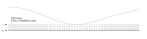
As opposed to PCM audio where the ADC sampling process takes the absolute value of the analogue voltage coming in to it at any given point, Pulse Density Modulation (PDM) instead works based on the time between two samples dictating whether the wave is increasing or decreasing in amplitude. If the samples are closer together, the wave is increasing in amplitude. If they are further apart, the amplitude of the waveform is decreasing. The absolute value of the waveform is not known per se when looking at an individual sample (as it would be with PCM), but put together the samples produce a good representation of the original waveform.

The caveat with this method is that the ‘dynamic resolution’ (the amount of information about the amplitude which is stored in any one sample of the audio) is incredibly low, being 1 bit, so the samples need to be taken at a much higher rate than with PCM audio. Where PCM typically samples at 44,100 samples a second, DSD works at a minimum of 64 times this rate, around 2,800,000 samples per second.

This process of encoding digital audio creates a lot more noise. This is due to both the low bit depth (which at 1-bit creates more quantisation noise) and the higher sample rate (essentially turning things on and off at a much higher rate creates noise). In order to make the format usable, the data is noise-shaped to clear the quantisation noise out of the audio band into the ultrasonic region (above 20kHz), where it cannot be heard.

image

The result is near 24-bit performance in the audio band (0 – 20kHz) and a signal bandwidth that extends beyond 100kHz. The price for the 1-bit approach is a very large amount of noise in the ultrasonic region (20kHz – 1.4MHz), but this is not normally heard as a noticeable background noise. This method of digitally encoding music is what is used in the format Digital Stream Direct (DSD). This format of 1-bit conversion is the basis of Bitstream Sigma-Delta Digital to Analogue Converters (which will be covered in a later post).

There are further developments into DSD audio, whereby higher and higher rates are used. The original rate, referred to as DSD/64 or Single Speed DSD, runs at 64x the rate of CD audio. DSD/128 or Double Speed DSD runs at 128x CD audio rates, and so on for DSD/256 and DSD/512.

DSD files, even at the standard DSD/64 rate are large. The data rate is 5644.8 kbps for 2-channel stereo.

This post is on the shorter side, but with the basic formats covered we can get on to the fun stuff. The next post will be on the basics of digital to analogue conversion, starting with Ladder DACs.

Part 3 - Introduction to D/A Conversion

13 Likes

Very nice, look forward to the next articles. Thanks for the effort.

Many thanks indeed, James.
An ‘online white paper’ on technical subjects is highly appreciated.
The dCS pro audio manuals (especially the one for dCS 974) were much more detailed than the current Hi-Fi manuals .

That is no doubt true.However dCS no longer supports the professional market. For those of us in the domestic audio sphere who are not engineers yet who now constitute the majority of dCS customers it s surely more important to have something we are able to understand and use than to provide large amounts of incomprehensible ( to us) technical verbiage.

You will also have noticed that dCS has simplified the user interface of the components over the generations and that options that were available with the first generation ( e.g. selecting between dither waveforms in the D to D converter ) are no longer catered for as they often really only had significance within a studio setting.

Part 3 – Introduction to D/A Conversion

DACs – Digital to Analogue Converters – are a crucial part of almost all modern headphone setups, in one form or another. They play a vital role in helping to translate the original musical performance of an artist to a listening experience for the end user. The fundamental concept of a DAC is to translate digital audio – whether it is streamed from Spotify or Tidal, stored on a DAP or played from a NAS – into an analogue voltage which is used to drive a transducer like headphones.

When making this digital to analogue conversion, there are two factors to consider: can the converter perfectly reproduce the original amplitude of the wave when it was recorded (in other words, can it output the right voltage), and can it do it at exactly the right time? Whether the converter can reproduce the correct voltage comes down to the DAC circuitry itself, and whether it converts the sample at the right time comes down to the clocking of the system. I will go through the DAC circuitry first, and clocking definitely warrants its own topic which we plan to cover next.

Digital audio is stored in binary format (effectively a series of 1s and 0s) as a series of ‘samples’. As we discussed earlier, the number of consecutive binary digits that are used to represent the original sound wave is called the bit depth. 16-bit audio, for example, has 16 consecutive binary digits, all either 1 or 0. A DAC needs to translate this binary number to an analogue voltage, as that voltage is what drives headphones to produce sound. It does so using a series of current sources – electronic components that each generate an amount of analogue voltage.

One of the most common approaches to D/A conversion is to have one current source always working for one of the digital audio bits exclusively. For example, one current source will always be following what the first bit in the digital audio signal is doing. Another current source will always be following what the second bit in the digital audio signal is doing, and so on for as many current sources as are needed. As the current sources go on, the amount of energy they must generate gets smaller and smaller (it halves for each consecutive current source).

When looking at a diagram of how these components would be laid out, it looks an awful lot like a ladder, hence the informal name these types of DACs have been given – Ladder DACs. To ensure that the voltage generated by each current source is incrementally smaller the further down the chain they are, resistors need to be used between current sources. The values and layout of these resistors gives name to the two prominent types of Ladder DACs – R-2R DACs and Binary Weighted DACs.

One very important distinction to make early on – a dCS DAC (the Ring DAC) is not a Ladder DAC. This difference will be explained later.

R2R DACs

R-2R DACs (a subset of Ladder DAC) use one of two resistor values to control the amount of voltage generated by each current source. Resistors of value R are used between each current source section, and resistors of value 2R are used on each current source. If a particular bit in the audio signal goes high (a 1 instead of a 0), the corresponding switch is enabled and that current source output goes high. The outputs of all current sources are then fed to a summing bus, which provides the overall output of the DAC.

image

Binary Weighted DACs

In Binary Weighted Ladder DACs, resistors of decreasing values are used to create increasingly small steps in power generated by current sources. If the first resistor has a value of R, the next would be 2R, then 4R, then 8R, 16R, and so on for as many steps as required. This hierarchy of resistor values is what gives this approach the Binary Weighted name.

image

The main drawback with both the R-2R and Binary Weighted DAC approaches comes from the fact that resistors (like all electronic components) have an element of error in their values. For example, a gold tolerance resistor guarantees the resistance of the component will be within 5% of its stated value. This means that for the resistors used in a Ladder DAC, the current generated by that section of the DAC could be either lower or higher than needed. The key point here is that a Ladder DAC uses the same current source for a given bit in the audio signal every time, meaning the error is exactly the same every time the bit goes high. Here, the errors in the component values are correlated to the audio signal. This results in an audible linear distortion of the signal, adding in unwanted harmonic components.

The issue with this is the fact that the larger current sources (correlating to the more significant bits in the audio signal) have the same margin of error as the smaller ones. In the case of a 24-bit ladder DAC, a 1% error in the most significant bit (MSB, or the largest current source) would be larger than the entire 7th bit, and 104dB louder than the 24th bit. The MSB needs to be accurate to 0.000006% to allow for 24-bit resolution.

One further issue Ladder DACs suffer from is Zero Crossing Point Distortion. Given that each current source has a potential correlated error associated with it, what happens when say in a 16-bit DAC we go from reproducing an amplitude of 32767 to 32768? The DAC changes from having the first (most significant) bit low and the following 15 bits high, to having the first bit high and the following 15-bits low. This is called the Zero Crossing point. The size of the errors associated with each current source / bit here – specifically the fact that the sum of the 15 errors with 32767 and the one error with 32768 – are both very large compared to the least significant bit (LSB). This means that the change from 32767 to 32768 in the DAC can be much bigger than one LSB. The result of this is linear distortion, which is extremely undesirable.

The solution to the issues posed by the linear distortion of a Ladder DAC is to remove the link between the original signal and the physical resistor value errors associated with specific sample values. How exactly this can be achieved will be discussed in the next post, where I will explore the architecture of the dCS Ring DAC.

Part 4 - The Ring DAC

13 Likes

Thanks for this James. Very enlightening.

Thank you. Very interesting!

Thanks very much for such clear explanations.

Forgive me going right back to basics - and possibly showing my ignorance! Could you “plot” the following audio file formats to show which of the two technologies (PCM & DSD) they are. I’m particularly interested to know:

  • flac - clearly shown as PCM technology on my Melco, but sometimes listed as
    “flac lossless” - is the reference to lossless reflective of a material audio improvement

  • .wav - I have a lot of .wav recordings transferred from my previous Naim server, and my Melco offers .wav as an alternative to flac when ripping new material. Is one superior over the other, particularly as downloads from the sites I use are exclusively flac and therefore transfers to Melco in .wav presumably involves conversion? Which would you choose in the context of playback on Rossini?

  • BBC HD broadcast (specifically Radio 3).

  • Are there other high quality formats that I should be aware of - either to embrace or avoid?

FLAC is an example of an audio CODEC (COmpressor DECompressor) that is used to reduce the file size / data rate of PCM audio that is being sent. FLAC is lossless, meaning there shouldn’t be any perceived change in the audio quality when comparing FLAC to an uncompressed format like .wav. The benefit is that the file sizes for audio tracks are much lower, meaning less hard drive space or streamed data to worry about, with the same sound quality at the other end.

.wav is a form of uncompressed PCM. Which you would choose really comes down to how much storage space you have available, as audio quality should be equal across that and FLAC.

BBC Radio 3 HD uses the AAC-LC codec, another method of compressing PCM audio for sending over the internet. I would be very surprised if anyone was streaming DSD audio - the file sizes are much larger than for example FLAC, which is fine if you are sending it locally from your NAS to your DAC, but to stream it over the internet to say a smartphone could be problematic.

1 Like

I would just add that AAC as used by BBC R3 is a lossy codec whereas all of the others file types mentioned in this thread are lossless. However the streaming rate used by R3 is high for this kind of thing - 320kb/s and that the subjective quality they can achieve is remarkable - try the Monday lunchtime recitals from Wigmore Hall as an example.

1 Like

Part 4 – The Ring DAC

How can the issues described previously with Ladder DACs be resolved? What would a DAC designed from the ground up to effectively de-correlate errors in the DAC itself and remove the resulting distortion look like? That is where the dCS Ring DAC comes into play.

The Ring DAC is the proprietary DAC technology found inside all dCS DACs. On the surface, the Ring DAC may look like a Ladder DAC. There is a latch and a resistor for each current source, and these current sources are fed to a summing bus. The key difference between the Ring DAC and Ladder DACs however, is that the Ring DAC uses current sources of equal value. This is what is known as a ‘unitary-weighted’ or ‘thermometer coded’ DAC architecture. Additionally, the Ring DAC does not use the same current source(s) for the same bit every time . There are 48 current sources within the Ring DAC, all of which produce an equal amount of current. The Field Programmable Gate Array (FPGA) controlled nature of the Ring DAC allows the sources to be turned on and off in such a way that any component value errors are averaged out over time. Firing the same bit three times on the Ring DAC might give one output slightly high, the next slightly low, the next somewhere in the middle, as opposed to outputting the sample slightly high every time, or slightly low every time (as seen in a Ladder DAC, for example).

It takes a considerable amount of signal processing power and know how to optimally operate a thermometer coded DAC, but the benefit with this approach is that it almost entirely removes the linear distortion from the signal (bear in mind that the highly artificial distortion many DACs produce is very noticeable to humans and has a negative impact on perceived sound quality).

The Ring DAC process may be thought of as decorrelating errors. Background noise (an uncorrelated error – one which is not linked to the audio signal itself) is very prevalent in nature, whereas artificial distortion (a correlated error) is not.

This results in the Ring DAC having class-leading distortion performance, particularly at lower signal levels. This means more fine detail can be resolved and heard in the audio.

The nature of exactly how the Ring DAC decides which current sources need to be turned on or off at any given point to generate the correct signal is dictated by a highly sophisticated set of rules defined in the dCS Mapper. While it may appear to be random, it is the culmination of three decades of continuous work, resulting in a carefully calculated set of patterns used to minimise noise, distortion and crosstalk while primarily keeping the highest degree of linearity by averaging out the contribution of components that fall out of specification over time. Improvements to the Mapper over time have allowed for a lower noise floor to be achieved, while maintaining the signature linear sound associated with the Ring DAC. The Mapper is what allows for the noise created by the Ring DAC to be pushed outside of the audible band of frequencies and then filtered out.

image
This diagram illustrates the basic layout of the Ring DAC.

The Mapper works at 5-bits, so PCM data which arrives at the Ring DAC is first oversampled to 706.8kHz or 768kHz. This is then modulated to 5-bits at a rate between 2.822MHz and 6.144MHz (depending on the unit, settings and content sample rate) and fed into the Mapper which distributes this signal to the current sources in the DAC.

image
This diagram illustrates the output of the Modulator within the Ring DAC, modulating incoming digital audio signals to a 5-bit high rate format ready for conversion to analogue.

The next post will begin to discuss filtering in DACs.

Part 5 - Filtering in Digital Audio

15 Likes

My confusion is with how the 16-24 bits of the input digital signal gets converted to 5 bits going into the mapper? It would seem this is a big loss in dynamic range resolution, so I must be missing something…

If I were to venture a guess, I’d say that “5-bit modulator” stage is a digital multibit sigma-delta modulator.

Looking forward to James’ reply :grin:

Many thanks, James, really helpful!

Am looking forward to the next instalments of your Technical Explanation papers.

Best wishes

Peter

Thanks Pete

All adds to my understanding!

regards

Peter