My confusion is with how the 16-24 bits of the input digital signal gets converted to 5 bits going into the mapper? It would seem this is a big loss in dynamic range resolution, so I must be missing something…
If I were to venture a guess, I’d say that “5-bit modulator” stage is a digital multibit sigma-delta modulator.
Looking forward to James’ reply 
Many thanks, James, really helpful!
Am looking forward to the next instalments of your Technical Explanation papers.
Best wishes
Peter
Thanks Pete
All adds to my understanding!
regards
Peter
Thank you.
I appreciate I don’t need to know this but I’ll ask anyway as it’s very interesting. Is left and right divided in the ring or can the latches switch sides.

By no means am I an expert on the maths behind this, however… The more appropriate way to describe the modulation stage would be as a “noiseshaper”, as the audio community is pretty firm on the definition of delta-sigma modulation with one specific implementation.
That said, the key aspect to consider is that even with DSD running at the same rate as the Ring DAC with only 1 bit, you get close to 24-bit performance. We are working with a much greater word length here, and while it really isn’t an apples to apples comparison (DSD to the Ring DAC format), it stands to show that a lower bit depth and higher rate – if handled correctly – can produce excellent results.
It is separated, yes – one side of the DAC board handles one channel of the audio. This avoids crosstalk between the left and right channels.
4 Likes
The following is taken from a response we put on another forum, but I think the information is really pertinent to the discussion here…
To improve the state of the art you need subject matter expertise. Only by understanding the benefits and limitations of various approaches to A-D and D-A conversion can we design a DAC that we feel is best in class. Of course what we deem as a critical performance requirement may not be the same as other manufacturers or hobbyist engineers, however we are one of a select few manufacturers who have designed world-class ADCs, DACs and sample rate converters for both studio and consumer use.
So, we are trying to point out the issues that exist in common architectures, which to sum up are:
You can have lots of weighted current sources at a low sample rate – the challenge here is matching these current sources, and keeping them matched over temperature variations and time. For audio, the side-effect of this is that any errors in this matching cause unnatural distortion (due to correlation), which the human auditory system is very sensitive to. On the plus side, because we don’t have to run that fast, jitter is less of an issue.
You can have conceptually a single current source, and run it at a much higher sample rate. This fixes the matching issue (because it’s self-referencing – on or off, and any drift will manifest as DC rather than distortion). Unfortunately to deal with the quantisation noise generated, you have to heavily noise shape this and move it up in band. This can cause issues because if you keep the clock at sensible rates, the quantisation noise is very close to the audio band, and if you move it too high in frequency jitter becomes a real issue (due to switching noise), at which point you may have to perform some quite horrible (and sometimes impossible) maths to match rates.
What the Ring DAC does is effectively a hybrid – the clock can run at sensible rates (so 3-6MHz) and the noise shaping can be gentle, but because we have multiple codes to represent, we need a way to match them exactly - whilst bearing in mind that components age, temperature can become a factor and so on. This is the job of the mapper, and it has numerous attractions, including distributing DAC errors away from where we are interested (audio frequencies) to where we are insensitive (very high frequencies), without altering the data presented to it, whilst at the same time ensuring all the sensitive components age in the same way.
We can definitively state the that the Ring technology is not multiple DSD streams, and is not random – if you read the writeup, we even say “may appear random”.
It is quite correct to say that you cannot decorrelate noise that is already part of the signal. However, it is worth thinking about this as a philosophical point. One view is that noise shaping and filtering are evil because they somehow ‘guess’ and don’t reproduce the ‘original’ signal, and the ‘fewest steps must be the best’. Now, this may sound strange coming from us, but one of our beliefs can be attributed to Einstein – “Everything should be made as simple as possible, but no simpler ”. So what is the original signal we are trying to reproduce? This will be covered more in the filtering article.
7 Likes
Right, that makes sense. Perhaps a more appropriate term I should’ve used is Noise-Shaping Requantizer. ![]()
2 Likes
@James the series seem to be halted. Will there be a next post?
I read this expanding thread with great interest, but fear like my understanding of Relativity, which I was taught at A level, I’m somewhat behind the curve. But it is very enlightening thanks.
Will you be at some future point explaining the effects of the filters ( for vivaldi). I’m a little lost despite reading round this as to what their sonic effects are and would be most interested.
Yes listening is recommended, but backing it up with some science would be much appreciated.
Cheers
The series is definitely still going ahead. The next post will be coming very soon, but we’re working on preparing some additional information that we hope will address some of the questions that we have received over the past few weeks.
Thanks for your patience, and I’ll be back with a new post on filtering within the next two weeks.
The next post(s) we have planned are on filtering, so once those are ready hopefully you will feel much more comfortable with the topic!
4 Likes
Part 5 – Filtering in Digital Audio
Most DACs will have some information in their specifications about the types of filtering they use. As these filters are an incredibly important part of the product, it is worthwhile explaining why and how they are used.
To understand why we need a filter, it helps to start at the beginning, when an analogue signal enters an ADC during the recording / production process. (This is significant, as the filter within an ADC has almost as much impact on what we hear during playback as the filter within a DAC.)
We have previously discussed how audio is sampled using an ADC – the analogue voltage is converted into a digital representation, with a series of ‘samples’ being taken to form this representation. The lowest sample rate used in audio is typically 44,100 samples per second (S/s). The reason for using this sample rate (44.1kS/s) is largely due to the Nyquist Theorem. This states that the sample frequency of digital audio needs to be at least twice the highest frequency in the audio being sampled. The highest frequency which can be sampled (half of the sample rate) is defined as the ‘Nyquist frequency’. As the human range of hearing extends up to 20,000Hz, accurately sampling this frequency range requires a sample rate of at least 40,000S/s.
However, what happens if what we are sampling doesn’t ‘fit’ into our sample rate’s valid range, between 0Hz and the Nyquist frequency? If this occurs, then the frequency components above the Nyquist frequency are ‘aliased’ down below it. This sounds counterintuitive, but it is illustrated here:
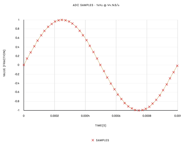
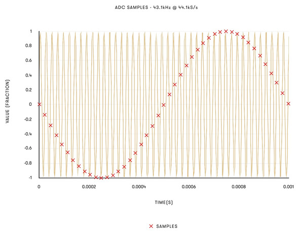
The above graphs show two signals: one at 1kHz and one at 43.1kHz, both sampled at 44,100 samples per second (44.1kS/s). Note that sampling the 43.1kHz signal produces samples which are indistinguishable from the 1kHz tone (though phase inverted). If this 43.1kHz signal was passed through the ADC, the resultant samples would be indistinguishable from those of the 1kHz tone – and a 1kHz tone would be heard on playback. This means that the ADC must remove anything which does not ‘fit’ between 0Hz and Nyquist frequency, to avoid these aliased images affecting the audio.
The removal of anything which does not fit between 0Hz and Nyquist frequency is carried out by way of a low-pass filter. This filter removes any content above a certain frequency, and allows anything below that frequency to pass through, ideally unchanged. This filter can be implemented in either the digital or analogue realm.
It would seem that the most obvious solution to the aliasing problem caused by running an ADC at a sample rate of 44.1kHz is to implement a filter which does nothing at 20,000Hz, but cuts everything above 20,001Hz. This would allow the removal of any unwanted alias images from the A/D conversion, while ensuring the audio band remains unaffected. However, such a filter is highly inadvisable. For one thing, if using a digital filter, the computing power required to run such a filter would be excessive. Filters work by reducing the amplitude of the signal above a frequency on a slope so to speak, measured in decibels per octave. As such, the audio is sampled at a higher rate than simply double the highest frequency we are trying to record (it is actually sampled at 44,100Hz instead of at 40,000Hz) which allows some room to filter it. This means the filter can now work between 20,000Hz and 22,050Hz without aliasing becoming an issue, while also leaving the audio frequencies humans can hear unaffected.
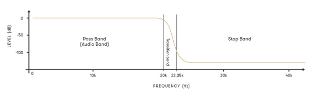
This diagram illustrates a low-pass filter for 44.1kHz audio.
This is still an extremely narrow ‘transition band’ to play with. If this is done with an analogue filter, the filter will have to be very steep – this is problematic as analogue filters aren’t phase linear (the filter will delay certain frequencies more than others causing audible issues) and are pretty much guaranteed to not be identical. This is okay when they are working at say, 100kHz, but at 20kHz this becomes very problematic. As such, the filter used to remove any content from the Nyquist frequency and up is implemented in the digital domain, in DSP (Digital Signal Processing).
In audio recording, it is common practice to use a high sample rate ADC and perform the filtering at the Nyquist frequency on the digital data instead. This method is known as an ‘Oversampling ADC’. The block diagram for a dCS oversampling ADC producing 16-bit 44.1k data is shown here:
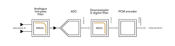
The analogue low-pass filter removes high frequencies from the analogue signal above 100kHz, as these would cause aliasing. As previously discussed, this analogue filter acting at 100kHz can be gentle and acts in a region where non-linearities are not as critical.
The ADC stage then converts the signal to high-speed digital data. In a dCS ADC, this stage is a Ring DAC in a feedback loop, so produces 5-bit data sampled at 2,822,000 samples per second.
The Downsampler converts the digital data to 16-bit 44,100 samples per second. This data then passes through a sharp digital filter, which effectively removes content above 22.05kHz. (Frequencies higher than this will cause aliases if not filtered out.) The PCM encoder then formats the data into standard SPDIF, AES/EBU and SDIF-2 serial formats, complete with status and message information.
The digital filter used in the Downsampler will have its own set of trade-offs to employ. To simplify this greatly, digital filters work by passing each sample through a series of multipliers, with these multipliers collectively acting to filter higher frequencies from the signal. The shape of how these multipliers are arranged is referred to as the filter ‘shape’ (symmetrical or ‘half-band’ filters, asymmetrical filters). Different filter shapes have different impacts on the sound.
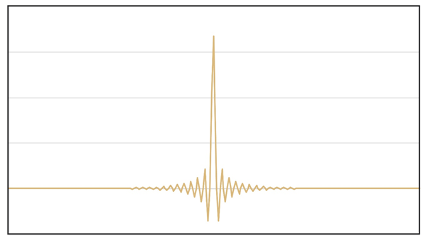
This diagram illustrates an example of the response of a symmetrical digital filter. They are called this as they produce symmetrical ‘ringing’ when driven with an impulse (also known as a transient). This results in an acausal response before the impulse. The effect is more pronounced at lower sample rates:
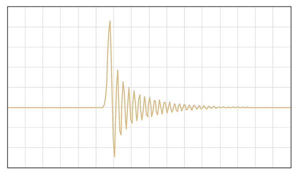
This diagram illustrates an example of an asymmetrical filter response. This filter type has a completely different impulse response – here, there is no ringing before the impulse, but there is more ringing after the impulse when compared to a symmetrical filter:
Given the fact that the ADC must use a filter to remove aliases, and that a digital filter acting at the Nyquist frequency is preferable to using a harsh analogue filter, there will therefore be pre- and/or post-ringing introduced at the recording stage by the digital filtering in the ADC. This is a good trade-off to make, and the filter choice here is important.
Most ADCs will work using a symmetrical filter. What this means is that for any digital recording, there will be (necessary) pre- and post-ringing present on the recording, as a result of the filter which was used. The key point to be made here is that all digital recordings will include ringing from the filters, even before they reach the DAC, but this is the best approach to take – provided the filters are correctly designed and implemented within the ADC.
The other side of this topic is the DAC, where the digital audio recorded by the ADC is translated back to analogue for playback.
When a DAC reproduces an analogue waveform from digital samples, an effect similar to aliasing occurs. This is where, due to the relationship between the frequency of the analogue audio signal and the sample rate of the digital signal, ‘copies’ of the audio spectrum being converted can be observed higher up in the audio spectrum. While these images exist at frequencies outside the range of human hearing, their presence can have a negative impact on sound.
There are two reasons for this. Firstly, frequencies at rates above 20,000Hz can still interact with and have an audible impact on frequencies lower down, in the audible spectrum (between 0-20,000Hz).
Secondly, if these images – known as Nyquist images – are not removed from an audio signal, then the equipment in an audio system may try and reproduce these higher frequencies, which would put additional pressure on that system’s transducers (particularly those responsible for reproducing high frequencies) and amplifiers. Removing Nyquist images means an amplifier has more power available to use for reproducing the parts of an audio signal that we do want to hear, which leads to better performance and a direct positive impact on sound.
Similar to in an ADC, the solution to the problem posed by Nyquist images in D/A conversion is to filter anything above the highest desired frequency of the audio signal by using a low-pass filter. This allows Nyquist images to be eliminated from the audio signal, without impacting the music we want to hear. The question of how a low-pass filter should be designed is a complex and sensitive topic –and it’s important to note that there is no one-size-fits-all solution.
Of course, when working with source material which is at higher sample rates than 44.1kHz, such as hi-res streamed audio, the requirements of the filter in the DAC change. There is a naturally wider transition band, and as such the filter requirements will be different. Most DAC manufacturers offer a single set of filters which are cascaded for different sample rates. Given the different filtering requirements posed by converting different sample rates, this is not the optimal approach to take in a high-end audio system.
For this reason, the filters found within dCS products and the Ring DAC are written specifically for each sample frequency by dCS engineers. Further to this, there are multiple filter choices available for each sample frequency in a dCS product. There is no one right answer to filtering, as it depends on the listener’s preference and the audio being reproduced, so a choice of very high-quality filters bespoke for the Ring DAC and the sample frequency of the audio are available for the user to choose from.
The next post will explore the details of how digital filters are designed for use in audio products, exploring factors such as cut-off frequency, filter length and windowing.
12 Likes
Very interesting, thanks James.
James this series is fascinating and I really look forward to the next part. One main feature is how well it is written, Even a dummy like me can understand it ( mostly ).
1 Like
Superb. Thanks so much James.
I’m in the middle of arranging a new hifi system after 35 years of not keeping up with that world and your DCS DACs were suggested as one possibility hence I’m reading your articles to understand why they are “different” and so much more expensive. So, my first question:
I don’t understand this issue — if your underlying digital representation is signed 16 bits (i.e, -32768 …32767) for input, how would you ever get a value of 32768 in the first place? In other words, this seems like a non-existent issue in reality and so it’s unclear why this issue would be even mentioned.
Thanks,
D
Digital representation is not signed.
Digital representation is not signed.
For a value of 32767 the lower significant bits 1 to 15 are required, highest significant bit 16 is set to zero.
For a value of 32768 only highest significant bit 16 is required, lower significant bits 1 to 15 are set to zero.
Thanks for responding.
Oh I see-- this is not about signed vs unsigned — this is an issue of changing 15 bits to 0 and one bit to 1?
If so, then why isn’t this a problem going from 2^n - 1 to 2^n for any value of n, not just when you are at 2^15 -1 ?
Changing all 16 bits is the worst case.